Wednesday 21 January 2009

Deferred Shading, AA, alpha blending. DirectX 9

Soon after finishing my DX10 demo, Arseny Kapoulkine gave me an idea how to implement the same functionality using DirectX 9.

In DX9 it is impossible to create a multi-sampled G-buffer, and access separate samples independently in a pixel shader. To use multi-sampled render target as a texture, you need to resolve it, and you won't have any control over this process. So, I had to create a super-sampled G-buffer - a buffer with width and height multiplied by the factor of 2, which will give us SSAAx4.

If you remember, this technique used SampleMask to select samples in which the data of transparent objects will be saved. This time, instead of it we will use stencil buffer.
Using alpha test and a simple shader that draws a grid in a following pattern at a per-pixel step (image is magnified):
Grid shader,
we fill up the stencil buffer with values of 1, 2, 4 and 8. This step is performed only once since the grid doesn't change.

Now, using only stencil reference value, we can render surface to a single sample of our improvised super-sampled buffer. And if we ever need to render it to more than one sample, stencil mask will come in hand.

Volumetric lightning was removed from DX9 demo, because it generated too many instructions (but it still could be computed, at a cost of rendering fewer lights per pass).

Another optimization is performed, using hardware early stencil or depth tests (can be switched using 'O' key).
Before rendering the full-screen quad with a shader that computes lightning, we use a different shader that along with alpha test and stencil (or depth) buffer, masks the pixels that don't require per-sample lightning and can live fine with per-pixel computation.
Masking shader checks if the values of 4 samples in a 2x2 block are equal, and if they are (within some epsilon), a more simple shader can be run, with a little quality cost and a large performance boost.

The same trick was added to the DX10 demo, and with multi-sampled buffer there is no quality lost at all.

On GPUs where early stencil test is not available (GF6, GF7), you have to switch to early depth test.
To run the demo you need GeForce6***+ or RadeonX***+.

Download .rar with sources, 341kb.

Some screenshots:


Demo controls:
WASD\Arrow keys - movement. Mouse - camera orientation.
'P' key - turn early stencil\depth optimization on and off. (Default: on)
'G' key - turn transparent surface rendering on and off. (Default: on)
'O' key - switch between early stencil and depth tests. (Default: stencil test)

Some results (minimum is for transparent surface occupying full screen, and the maximum is when none of the transparent surfaces are seen).
7600 GS, GT: 2-4fps
8600 GT: 2-55 fps
9600 GT: 10-200 fps

X1950: 36-91 fps
HD 2600: 25-70 fps
HD 4850: 110-232 fps

On NVidia hardware, the shader with per-sample frequency light computation works much longer while having only 4 times more instructions than the simple one. I expected a maximum of 4 times slowdown. The reason for this is still unknown. If the fps drops dramatically, it is recommended to turn off transparent surface rendering leaving only Deferred Shading and Antialiasing on.

Wednesday 14 January 2009

Deferred Shading, AA, alpha-blending.

While playing GTA IV I couldn't help but to notice the use of Alpha to Coverage. For the last few years I've seen this feature used mainly to create smooth edges for alpha-tested polygons when FSAA is enabled1. In the game, however, it is used for in and out object fading, and for a part of transparent objects as well. As far as I know, their engine uses deferred shading rendering, so this method looks rather interesting and gave me some thoughts about implementing those features, mentioned in the topic, that don't live quite well with deferred rendering method.

So how did I do this? I've seen some nice demos from Humus that shows transparent objects in deferred rendering using method similar to depth peeling. To implement something like this, we need to be able to access every single sample in our multisampled G-buffer, so I've opened DX help along with tutorials 01 and 02, and started to write a demo under DX10 where such features are available.

My first idea was that during the G-buffer fill-up, for transparent objects we will explicitly set SampleMask with the number of active samples that relatively to the overall sample count, nearly corresponds to the alpha value (so, with AAx8 it will be possible to have 8 levels of transparency). Straight away, I've stumbled across some problems with transparent objects being placed in multiple layers. So I had to manually hard-code sample masks with randomly distributed active samples to get the result look right.

In the shader where lightning is computed, for every sample, I calculated two-sided diffuse lightning (using alpha value to linearly interpolate between sides), specular and simplified volumetric lightning. The weight of every sample is 1/sample count. At this point, I have realized that I can set different weights for different samples and after that it is possible to write every transparent surface information into a single sample in G-buffer. I used a simple formula to convert pixel alpha to sample weight, because they aren't equal parameters.
This new method didn't solve the order-independent transparency problem, but made things much easier, now it is possible to set AAx4 while still able to render 4 layers of transparent geometry and the alpha value isn't restricted to 8 levels any more.

As the result I have a demo along with sources that could be run if you have video card with DX10 support and Vista\Windows7 operating system:
Download, 335kb.

Some screenshots:
first
second
third

It's just a demo without pretending to be used in real-world applications (at least for today). There is a lot memory usage for the multisampled G-buffer, and a lot of bandwidth is required.
If the demo speed is satisfying, you can set a LIGHTS constant in "Shaders\LightPS.txt" file up to 32.

1 AntiAliasing with Transparency
2 Stencil-Routed K-Buffer
3 Volumetric lighting demo

Monday 14 July 2008

Using ATI hardware tessellation in DX9.

Maybe you heard that ATI GPUs starting from 2*** have hardware tessellation unit. Maybe you have seen it working in GPU Mesh Mapper and Render Monkey 1.81. But there isn't any info on how to use it yourself. So with the power of reverse engineering I have finally written my first application that uses hardware tessellation. And I will gladly share the info with you.

To enable tessellator, simply write a few lines of code.
dev->SetRenderState(D3DRS_POINTSIZE, 0x7FA03001);
dev->SetRenderState(D3DRS_MAXTESSELLATIONLEVEL, *(DWORD*)(&floatTesselationFactor)); //from 1.0f to 15.0f


There is however, one issue. If you are changing the primitive type of the geometry, you need to disable tessellation:
dev->SetRenderState(D3DRS_POINTSIZE, 0x7FA03000); //Other values can do the same
dev->SetRenderState(D3DRS_ENABLEADAPTIVETESSELLATION, 0);

And after that, enable it again.

Before you try this out, you also need to change you vertex shader. Now you will get not a single vertex data, but the data of all three vertices of a triangle and barycentric coordinates inside it.

So, if you have something like:
struct VS_INPUT
{
float4 position: POSITION0,
float2 texcoord: TEXCOORD0
};


as your vertex shader input, change it to:

struct VS_INPUT
{
float3 barycentric: BLENDWEIGHT0,

//First vertex
float4 position1: POSITION0,
float2 texcoord1: TEXCOORD0,

//Second vertex
float4 position2: POSITION4,
float2 texcoord2: TEXCOORD4,

//Third vertex
float4 position3: POSITION8,
float2 texcoord3: TEXCOORD8
};


Now, to find parameters for current vertex, use:

float4 position = position1 * barycentric.x + position2 * barycentric.y + position3 * barycentric.z;
float2 texcoord = texcoord1 * barycentric.x + texcoord2 * barycentric.y + texcoord3 * barycentric.z;


Have fun with it!

Saturday 21 June 2008

Vector representation of fonts on GPU.

Recently, an idea to create GPU accelerated rendering of vector images occurred to me. These images contain not the color data itself, but the information about contours that form the final image. This vector image can be scaled without loss of detail.

Usually to render text on GPU, people use textures with glyph images in them. If you want to draw large scale symbols, you will have to increase the size of the image or scale the small one using bilinear or point filtering. I realized that it would be interesting to implement text rendering using vector fonts. Shader model 2.0 has some limitations, so I decided that I would support only black and white fonts.

To implement this I had to write a small tool that saves the information about the glyph outline (obtained using GetGlyphOutline function from WinAPI) into a texture. I also developed a software rendering prototype for testing.

GetGlyphOutline returns different representation of data for different parts of a glyph. If the part of the contour contains only straight lines, the list of points is returned. But for curved parts this function returns quadratic spline data. I decided to transform them into several straight lines, so the output data will be uniform. I found the equations in MSDN.
@ sign contour from GetGlyphOutline function

At first, I didn’t know how to determine if the given point is placed inside or outside a contour. Solution came shortly after: we will take line segment starting from arbitrary position (x;y) and ending at (+inf;y), and we will find number of intersections between line segment and glyph contour. Is the number is odd, the point is inside the outline and thus black.

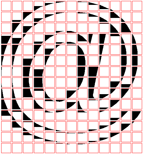
But it is not so simple. You can’t just put the list of all segments into a texture and force GPU to make hundreds (or even more) texture samples for every fragment. At first, I wanted to write only single line equation into one texel which it crosses. But in that case the resolution of final texture will become too large, to make all small details distinguishable. The solution for the problem is to break glyph contour into small blocks with a limited number of line segments inside single one:
@ sign outline, divided into small blocks (32x32)

Line segment intersections will be done separately for every block. But if you divide outline like it is shown on the image above, you won’t get anywhere far from this:
Incorect @ sign rendering without additional line segments

For example, for the block in the center of the first row there isn’t a single intersection found at any position, the number of intersections is zero and the decision is made that they all are outside the outline. The situation is fixed by adding additional line segments at the right side of the block for the regions that are originally inside the glyph outline.
@ sign contour with additional line segments added at the right side

Sounds simple enough, but to make it work I had to write some scary code. :) And before you rush to write line segment information to file, you need to reduce their count for every block. I decided to save no more than eight line segments, and luckily, only a small amount of blocks have broken this limit. I reduced their number in two stages. First stage removed all horizontal segments, because they don’t have any influence on the result. Second stage removed line segments, starting from the smallest one and only if the following requirements are met: the starting and ending points are the ending and starting points of two segments, accordingly. Thus I could remove a segment without leaving any gaps.

A line segment is represented with four numbers. For the first GPU implementation I decided to write single line segment information into a single RGBA texel. One block data occupied a small 8 pixel row. If line segment count was less than 8, a segment (0;0)-(0;0) was saved to all redundant pixels. First shader without optimization was compiled to 120 ALU instructions, so to run it, I had to temporally choose ps_3_0 profile. Here is the code of this shader:
1st revision

In the beginning of the shader you can see some strange manipulations with texture coordinates. The purpose of this is that for texture coordinates that point to a single line of 8 texels we need to get texture coordinates of the first texel in a group. We also get coordinates that show where we are in a block.

You can see that I used a different approach to define if pixel belongs to inside or outside parts of the outline. By default, we are outside the outline (white color, wind = 1.0), and with every intersection we multiply wind by -1.0; so we are changing white to black and vice versa. This is a bad decision; it is hard to optimize the chain of 8 dependent multiplications. I used it here, because I actually didn’t invent the normal approach at the time of writing. :)

More to that, we do not exploit the ability of GPU vector processors to process 4 float numbers simultaneously, and to fix this I had to change the data representation in texture. I had to write data in a way that you can get information of the one component of 4 line segments in one texture fetch. Line segment is represented using four numbers (x1; y1)-(x2; y2). I saved them in a slightly different order {x1; x2; y1; y2}, but this isn’t significant. In addition, a few operations were performed in preprocessing tool and vertex shader. Unfortunately, there is no vector division instruction; that could have saved me 6 instructions, which is a lot. Optimized shader compiles to 42 ALU instructions and runs in ps_2_0 profile.
2nd revision

It's time to see the results!

Vector texture for Arial font resulted in 512x512 image, and only 55% of the space is used. Maybe I could have packed the glyphs tighter to reduce the size to 512x256. Image size is 1Mb and it can be compressed to 43kb using WinRAR. I haven’t tried to save the image into compressed dds, because the result will certainly be wrong.

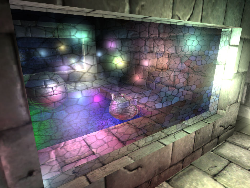
Here is the render of vector image:


And close-up of one glyph.


The method has some disadvantages:
There is no smoothing and the font looks bad when minified (following demo will show hand-made SSAA to smooth the image). Maybe it is possible to implement some smoothing inside a shader, but at the moment I don’t have any good ideas on how to do it.
There are only two colors (arbitrary, not only black and white).

My implementation shows vector textures that are used for font rendering, but it can be applied to any other two-color vector image.

Some people asked me to make a demo (My first GPU implementation was written as an effect for ATI Render Monkey), and here it is. You can download archive here (109kb).

Move the plane by dragging the mouse or by pressing Arrow keys.
Zoom in and out using mouse wheel or +/- buttons.
'A' button will toggle improvised 8x supersampling (render is performed eight times with subpixel shifts and additive blending). Its impact on speed is as dramatic as the impact on quality:


You can also find source code for the render, but not for the preprocessing tool.
You do not need D3DX to run this demo.

On ATI 2600XT I get 640/92 fps (no SSAA/SSAA). I would like to see results on your hardware.

For further reading:
Hugues Hoppe, Texel Programs For Random-Access Antialiased Vector Graphics.

Tuesday 26 February 2008